2.3 LIN Cluster
A LIN cluster is defined as a number of LIN nodes connected through a physical cable. LIN clusters consist of 1 master and up to 16 slave nodes.The LIN bus connects a single master device (ECU/node) and one or more slave devices (ECU/nodes) together in a LIN cluster. All Signals in a LIN Cluster are defined in the LIN Description File(LDF).
-
Add LIN cluster→ Short Name → Baudrate(Bits/s) → Protocol Name → Protocol Version → Speed → Save.
-
LIN Cluster sub points ECU connector, Frame Triggerings and Schedule Table.

2.3.1 ECU Connector
-
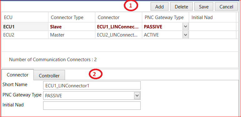
Add ECU → Connector Type (Master or slave) → Connector → PNC Gateway Type(Active,None and Passive)→ Initial Nad → Save.
-
Connector and controller two parts are there. Controller part Controller Type → Wakeup By Controller Supported (True or false) → Protocol version –> Configured Nad –> Function Id → Supplier Id → variant Id → Save.
2.3.2 Frame Triggering
-
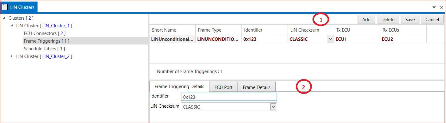
Add Frame or select Frames (LIN Sporadic Frames, LIN Unconditional Frames and LIN Event Triggered Frames) → Short Name → Frame Type → Identifier → LIN Checksum(Classic and Enhanced) → Tx ECU → Rx ECU →Save.
-
Frame Triggering Details → ECU Port(Here we select Tx and Rx ECUs) → Frame Details available.
2.3.3 Schedule Tables
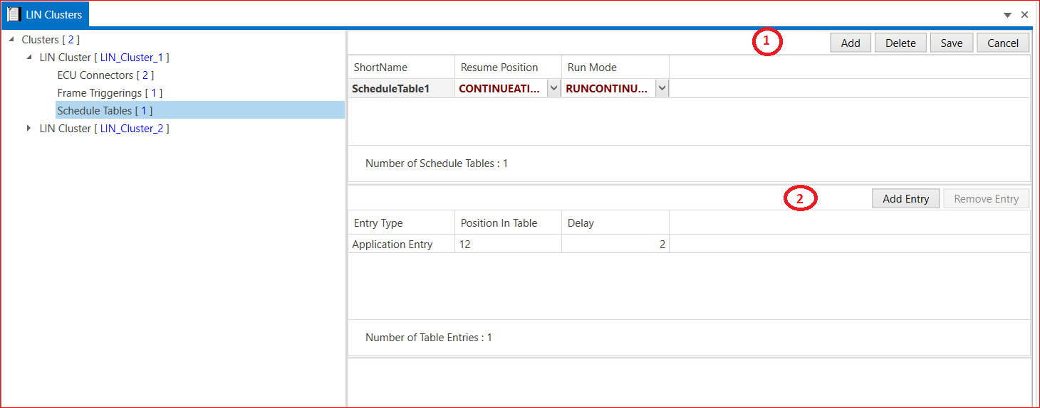
- Add schedule table → Short Name → Resume Position→ Run mode→ Save. Add Entry→ Select LIN Frame Triggering→ Enter Type→ Position in Table→ Delay → Save.